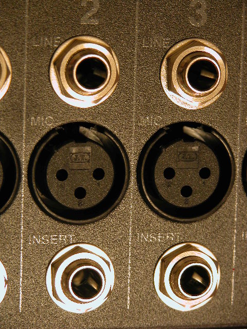
The top row of jacks on the mixer are for 1/4" inputs for line level inputs. In general, the LGB&D will not use these inputs.
The second row of jacks are XLR inputs for balanced Mic inputs. These are the jacks that the LGB&D's mike snake will be plugged into, or that the LGB&D's mikes can be plugged directly into.
The third row of jacks are called channel inserts. The compressors plug into this row of jacks to enable compression on a specific input channel. The LGB&D can plug compressors into 8 input channels.

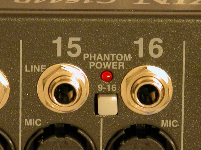
There are two Mic Phantom Power Switches and LED's in the section containing the
jacks. Each switch enables or disables phantom power for condenser
microphones. One switch controls phantom power to Mic inputs 1 - 8 and the
other switch controls phantom power to Mic inputs 9 - 16. The phantom
power switches have no effect on the Line input jacks or the Inserts
jacks. Phantom Power will not be needed by the LGB&D and so these
LED's should be off.
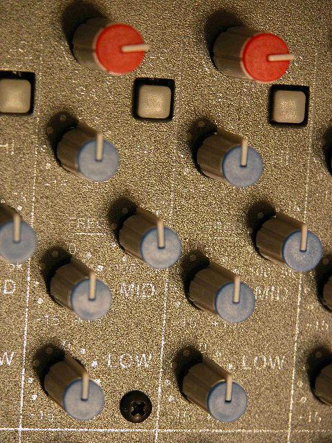
The next set of controls on the mixer input channels are the channel gain and EQ
controls.
The channel Gain control is colored red. It is used to set the input level for the channel. Setting the Gain too high may cause sound distortion and will cause the channel Peak LED to flash. The Gain for each channel should be set just below the point where the Peak LED would flash. Set the Gain by pressing the PFL switch and adjusting the Gain to 0db on the LED meter output.
The Lo Cut button is a filter that can help to eliminate unwanted low frequencies below 75 Hz. If the amplified sound from the channel sounds "boomy" try using this filter.
The next three controls are the channel EQ and are colored blue. The channel EQ will boost or cut a particular frequency range by up to +- 15db. The High EQ control affects 11kHz - 20kHz, the Low EQ control affects 20Hz - 80Hz, and the Mid EQ control affects 100Hz - 5kHz depending upon the Mid Sweep setting.
The Mid Sweep control is slightly smaller and set to the right of the Mid control. The Mid Sweep control selects the frequency that the Mid control boosts or cuts.
All controls are shown at their default starting position. Note that the red Gain controls will very likely need to be immediately adjusted for each channel.
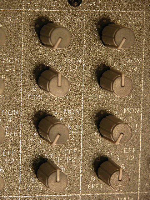
The next set of controls are the channel monitor and effects controls and are
colored grey. These controls are pre-EQ and pre-Fader. That means
that the EQ settings and position of the channel fader control do not have any
impact on the Monitor mix.
The first control is for Monitor 1. The Off position is full counterclockwise. Turn this control clockwise to mix this channel into the Monitor 1 output signal.
The second control is the Monitor 2 AND Monitor 3 control. The Off position is center. Turn this control counterclockwise to mix this channel into the Monitor 2 output signal. The LGB&D will not be using Monitor 3.
The third control is the Monitor 4 (Alt Effects 2) control. The Off position is full counterclockwise. The LGB&D will not be using Monitor 4 or Effects.
The fourth control is the Effects control. The Off position is center. The LGB&D will not be using Effects.
All controls are shown at their default starting position.
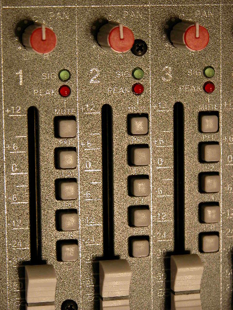
The first control is the Pan control and it is colored red. The Pan control will be primarily used to manage the balance of the input signal being sent to the main L/R (left/right) mix and main speakers.
The green SIG LED is the Channel Signal indicator. It is post-EQ and pre-fader. It lights when an input signal for the channel has been detected. It is a good way to determine if the mixer is getting an input signal it can mix from the channel.
The red PEAK LED is the channel Peak indicator. It is post-EQ and pre-fader. It flashes when the input signal is peaking, distorting the input signal, and indicating a need to reduce the channel Gain.
The first push button is the Mute button. When pressed, the red Peak LED will light solid red to indicate that the input channel is not being sent to the main L/R or monitor mixes.
The second push button is the PFL (Pre-Fade Listen) button. The PFL button enables you to listen the channel in the headphones and view the channel on the LED meter output.
The next three sets of push buttons are the channel assignment buttons. These buttons assign the input channel to an output mix. There is a separate assignment button for the main L/R (Left/Right), sub-group 1 & 2, and sub-group 3 & 4. The LGB&D will only be using the main L/R assignment, the two sub-group assignment buttons should not be selected.
The channel fader is the last control in this section. It is the slider control. The channel fader control adjusts the output level of the channel for the outputs selected by the channel assignment buttons.
When the mixer is first being powered up all channels should be muted, all L/R channel assignment buttons selected, all PFL and sub-group assignment buttons de-selected, and all faders pulled down.
